Friday, November 23, 2012

AC Phase Control - TRIACs

I've made an AC Dimmer circuit using a TRIAC to experiment with AC Phase Control.
It uses an Arduino to control the TRIAC gate firing.

The situation here is: 120 vac, 60Hz.
This is an application of what's known as "random fire" (or random-firing) technique for full phase control. The term random is kind of misleading. Dimming cannot be effected by triggering the gate indiscriminately; triggering (firing) must be done synchronized with the line frequency. The line frequency is detected by finding the zero-cross, the point where the line voltage is at or near zero, which occurs with each alternation (half-cycle).
The resistor on U1's input (between AC Line and U1 pin_1) is 18.6 kΩ.  I used 3 6.2 kΩ (1W) resistors in series.  [The value wasn't specified on the schematic, prompting my doing so here.]
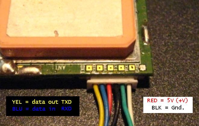
The Arduino gets zero-crossing pulses from U1's output at D2, one of its hardware interrupt pins.
The delay angle is selectable via two DIP switches. The default is 1 msec and the DIPs are binary weighted [i.e. delay time = 1msec + 1, 2, or 3 msec more.] With that, the conduction angle can be set to approximately 158, 135, 112, or 90 degrees.
Obviously, more resolution could be had with more switches, that's academic enough, but my objective was not some high degree of (or seemingly continuous) variability. This is a research project and these few well-defined options are sufficient.

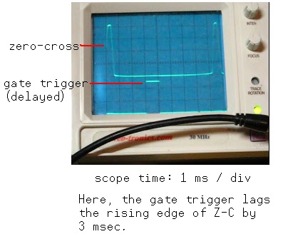
The zero-cross signal is awaited, its occurrence initiates the Interrupt whereupon the DIPs are read and thereby the delay time determined, then shortly the Gate signal pulses after the appropriate delay time and the process repeats.
As there's a snubber across the TRIAC and a snubber for the gate, too, I do intend to try it all out with a fan. That's my plan. But I confess that I'm squishy on it right now - preferring to bask in the glow of my present success before plunging into a power factor situation.
Before that, though, I want to take some pictures of the TRIAC output on the scope.

//     ***  Triac_03  ***
//
//  It's Working!  17 NOV 2012
//  gateEnable output lags
//  Triac_cue [zc] by 1-4 msec
//  via DIPSW1,2
//


byte gateEnable = 3;     // alias output
byte DIPSW1 = 4;         // alias input
byte DIPSW2 = 5;         // alias input
byte GatePulseTime = 1;  // at or near Alt start
int timesel;
volatile boolean zeroCrossed = false;  // flag


void setup()
{
  pinMode(DIPSW1, INPUT);
  pinMode(DIPSW2, INPUT);
  pinMode(gateEnable, OUTPUT);
  attachInterrupt(0,Triac_cue,RISING); // Ext_Int on D2
}


void loop ()
{
  if (zeroCrossed == true)
  {triacTrigger();}
}

// ----- The Interrupt -----
void Triac_cue ()
{zeroCrossed = true;  } //


void triacTrigger ()
{
  DIPread();
  delay (GatePulseTime);
  digitalWrite(gateEnable, HIGH);  
  delay (1);
  digitalWrite(gateEnable, LOW);
  zeroCrossed = false;  // flag reset
}

void DIPread ()
{
  GatePulseTime = 1;
  timesel = digitalRead(DIPSW1);
  if (timesel == HIGH)
  {GatePulseTime = GatePulseTime + 1;}
  timesel = digitalRead(DIPSW2);
  if (timesel == HIGH)
  {GatePulseTime = GatePulseTime + 2;}
}


I have been using "TRIAC", my preference. Should I use Triac when it's the first word of a sentence and triac otherwise? A textbook of mine, "Industrial Solid-State Electronics", uses the latter.

26 NOV 2012  The results with a 40W lamp are really good, but managing a string of LED holiday lights leaves much to be desired.  At 90deg, they were practically off.  I'm speculating, but I think that the LEDs, being a low-current affair, can't make the TRIAC's holding current and end up dropping out prematurely.
26 NOV 2012 (Pt. 2) I ran the LED holiday light string along with a 40W lamp and had much better results.  So, it's the holding current - the LEDlights don't draw enough (not one string, nor two.)
27 NOV 2012  So, here's the last on the LED holiday lights.  It came to me that I didn't need to use a TRIAC at all. Given the low current of these LEDlights, the triac driver (MOC3023) itself is sufficient. The zero-cross reference is still required and the MOC's logic input has to be kept active for the entire time of the conduction angle.

Here's the schematic of the modification.


This is the test "sketch", it's very coarse, just enough to prove the point. If you need gradual, put more work into it.
N.B. It doesn't use the switches, that part of the original circuit is not needed.  It loops through some chosen values, dwelling at each, and repeating the cycle.
[None of the sketches listed or referred to from hereon have need of the DIPswitch circuit.]

byte gateEnable = 3;     // alias output
byte GatePulseTime = 1;  // delay time till start
                         // 1 = brightest
byte PW = 0;             // conduction angle
int index = 0;
volatile boolean zeroCrossed = false;  // Interrupt Note

void setup()

{
  pinMode(gateEnable, OUTPUT);
  attachInterrupt(0,Triac_cue,RISING); // Ext_Int on D2
}

// ***** ***** ***** ***** //

void loop ()
{
  if (zeroCrossed == true)
  {triacTrigger();}
}
// ***** ***** ***** *****

// ----- The Interrupt -----

void Triac_cue ()
{zeroCrossed = true;}   // !!!
// ---- ---- ---- ---- -----
// ---- ---- ---- ---- -----
void triacTrigger ()
{
  fade();
  delay (GatePulseTime);
  digitalWrite(gateEnable, HIGH);   
  delay (PW);
  digitalWrite(gateEnable, LOW);
  zeroCrossed = false;  // Reset
  index ++;
  if (index > 720)
  {index = 0;}
}
// ---- ---- ---- ---- 

void fade ()      // GatePulseTime + PW must total 8 (8msec)

{
  if (index < 120)
  {
    GatePulseTime = 1;
    PW = 7;
  }
  else if ((index >= 120) && (index < 240))
  {
    GatePulseTime = 2;
    PW = 6;
  }    
  else if ((index >= 240) && (index < 360))
  {
    GatePulseTime = 3;
    PW = 5;
  }  
  else if ((index >= 360) && (index < 480))
  {
    GatePulseTime = 4;
    PW = 4;
  }
  else if ((index >= 480) && (index < 600))
  {
    GatePulseTime = 5;
    PW = 3;
  }
  else
  {
    GatePulseTime = 6;
    PW = 2;
  }
}
30NOV2012 Still sidetracked on this holiday LEDlight fading. 
I knocked out a better "sketch", the fading levels go up/down

byte MOC_logic = 3;  // alias output
byte Intensity;      // conduction angle
byte startPosition;  // delay time till start
int index = 0;
volatile boolean zeroCrossed = false;  // Flag

void setup()
{
  pinMode(MOC_logic, OUTPUT);
  attachInterrupt(0,cueStart,RISING); // Ext_Int on D2
}

// ***** ***** ***** ***** //
void loop ()
{
  if (zeroCrossed == true)
  {enableOutput();}
}
// ***** ***** ***** ***** //

// ----- The Interrupt -----
void cueStart ()
{zeroCrossed = true;}   //  !!!
// ---- ---- ---- ---- -----
// ---- ---- ---- ---- -----
void enableOutput ()
{
  fade();
  startPosition = (8 - Intensity); // "delay angle"
  delay (startPosition);
  digitalWrite(MOC_logic, HIGH);   
  delay (Intensity);               // "conduction angle"
  digitalWrite(MOC_logic, LOW);
  zeroCrossed = false;  // Reset
  index ++;
  if (index > 240)
  {index = 0;}
}
// ---- ---- ---- ---- 
void fade ()
{
  // not a lot of difference between
  // Intensity = 6 and Intensity = 7
  if (index < 30)
  {Intensity = 6;}
  else if ((index >= 30) && (index < 60))
  {Intensity = 5;}    
  else if ((index >= 60) && (index < 90))
  {Intensity = 4;}  
  else if ((index >= 90) && (index < 120))
  {Intensity = 3;}
  else if ((index >= 120) && (index < 150))
  {Intensity = 2;}
  // Intensity = 1 is very low
  // fade up   
  else if ((index >= 150) && (index < 180))
  {Intensity = 3;}  
  else if ((index >= 180) && (index < 210))
  {Intensity = 4;}
  else
  {Intensity = 5;}
}


Here's a solid demo, there are scope traces in addition to lights
Here's a scope trace - for good measure (Ha!)

30 NOV 2012 (Pt. 2)  I hooked the TRIAC circuit up again and used it with the immediately previous "sketch" and it works!
I think that this time I really will get out of the 'holiday lights' tweak.
30 NOV 2012 (Pt. 3) Crap! I have to walk that back some.
I had put the scope away, but I decided to bring it back out and have a look.  Despite improved fading over the way it was before, I saw on the scope that it was only conducting on one alternation, asymmetrical.  Then I plugged the 40W lamp in with it and it looked even better than the MOC3023 does.  It's totally textbook with the lamp plugged into it.
So, one "strand" isn't enough to do it with the TRIAC.  My strand takes 20ma.  My TRIAC (BCR8N) spec has both holding and trigger current of 100ma, which means a load of at least 12w. Looks like TRIACs with the lowest holding currents are also of the "sensitive gate" type.  There are many Standard types, 400V, 25ma - search Digikey.
I am using this particular Triac because I bought a few on a whim once.
[Maybe 5 strings would do it to it, but I don't have that many to confirm. A resistor might fix it, but it won't present the PTC characteristic (cold = low ohms, hot = high ohms), which it seems would be beneficial at low voltage, but maybe not essential, there has to be a substantial voltage present for the LED string to light up anyway.]
Still, no kidding, the MOC3023's aren't a bad way really are a good way to go for this application.
Good night.
01 DEC 2012  Here's a demo of a TRIAC output, the classic wave-forms you expect to see (running from the same sketch above)
You see that the TRIAC switches off better than the SBS output of the MOC3023 (it's depicted in the data sheet with a TRIAC-like symbol, instead of the SBS symbol, but it is a light-activated SBS.)
Be that as it may, the circuit the TRIAC is controlling needs to be drawing appreciable current or the TRIAC is unhappy. Maybe I should have demo'd that part, too?
* Here I can add, and do confirm, that the TRIAC output is just as solid by pulsing the Gate, at the beginning of the conduction angle - the method used with the very first "sketch" up at the top (it's labelled "Triac 03".)

I made a lot of assumptions about Triacs, I took a lot for granted, but I now have an appreciation for trigger current and holding current, at least I think I have a lot better handle on that than before.  Hadn't ever designed with them, they were always a "working or not working" proposition.  I certainly had the lamp dimmer going good, then I got sidetracked on the 'holiday LED lights' and got educated almost by accident.

I need to get back to my plan - running the fan. I was reading an app-note from ST and from what I gather, given an inductive load, the Gate should not be pulsed, but held on (given "ELI".)

09 DEC 2012  I still haven't run the fan. But I was making some H11/3023 boards and I used 2K resistors instead of 1K on the 3023 logic/input - and that skrewed it up. I swapped those out with some 470Ω that were on my bench and that brought things right (same as before.) That light-activated SBS is light-dependent for sure, it's like CTR with a photo-transistor output.

22 DEC 2014  Two years later! (Hard to believe.)
I have some VO2223 "power photo-triacs" to try out. I plan to mess around with those this weekend.
I've had the light-string up at work and I developed a new "sketch" - it has two routines for fade up/down (two speeds) and two routines for blinking (fast, slow).
Look for lightstring03 in my Where's The Code? page.

04 JAN 2015  OK, I finally got a VO2223 circuit together. I found out that they need more input current. With a 40w bulb I was only getting 60v when on with 4-5ma input. Running that up to 10ma got me over that hurdle. I need to incorporate this with a zero-cross board of its own.


All constructive Comments are encouraged (and encouraging)!

Saturday, October 20, 2012

PMB-688 GPS


The Polstar PMB-688 is a great GPS receiver. Though its documentation is less than a cup running over, it's knowable nonetheless.
From what I've seen, getting the wires right is the biggest problem. I think that that stems from a general and disheartening disregard for the documentation ( Polstar PMB-688 [PDF Alert] ), substituting for it an intellectually conceited, and lazy, conflation of the silkscreened labels by the square pads above the connector with the wires coming out of the connector assembly. So, here it is, unequivocally: Those labels DO NOT correspond to the connector wires!


Click pic to enlarge.

You don't have to believe me - Get out an ohmmeter and trace the wires to the pads.

The PMB-688 has only TTL I/O available. The Yellow wire is data out (TXD) and the Blue wire is for data in (RXD).
The Red wire is for +5, the Black wire is for Ground.

(It works out like this for the PMB-648, too, but "RS232" TX/RX are available on it.)

Here's the document's wiring diagram and an enhanced version of my devise beside it.


22 OCT 2012 - Had it on the oscilloscope, over the supply range of 3 to 5V, TX was 0/3V signal.

26 OCT 2012 - My only interest for a certain project is the RMC sentence.  The '688 default config is with GGA. GLL, GSA, GSV, and RMC enabled.  Heretofore, I've used the SiRF Demo, solely, to configure the '688 with.  The sentences can be disabled from the SiRF Demo, but if the GPS is left unpowered for 2-3 days then it reverts to stock config.
Q) What to do?
A) Make the config part of the initialisation in the programme.
Q) How's that?
A) Send the following data (4800 8N1):
$PSRF103,0,0,0,1*24<CR><LF>  --  disables GGA
$PSRF103,1,0,0,1*25<CR><LF>  --  disables GLL
$PSRF103,2,0,0,1*26<CR><LF>  --  disables GSA
$PSRF103,3,0,0,1*27<CR><LF>  --  disables GSV
and, if for some reason you need to
$PSRF103,4,0,0,1*20<CR><LF>  --  disables RMC
<CR> is Carriage Return, ASCII $0D (or 0x0d), or \r
<LF> is Line Feed, ASCII $0A (or 0x0a), or \n
The number after the asterisk is the checksum.  I found a great tool, it's at -
 http://nmeachecksum.eqth.net/
Another invaluable GPS site, most everything about anything NMEA --
http://www.gpsinformation.org/dale/nmea.htm

Saturday, October 6, 2012

High-side Switching


A lot of people feel, howbeit superficially, that they "get" NPN operation - the NPN conducts when its Base is at a potential more positive than its Emitter. Understanding a "high-side switch" supposes knowledge of PNP transistor operation.
Comparatively, the PNP is a little understood device. Looking back at some textbooks, they're never presented inside the "+V and GND" paradigm. The PNP is presented with an electrode connected to a negative voltage (gasp!), which provokes apoplexy and panic, or it gets mentioned in passing ("..there are PNP transistors, too, but you won't see them much and I don't like them, so let's move on..") and so is left to languish in obscurity, something to be avoided (ley de hielo.)
The PNP conducts when its Base is at a potential less positive (more negative) than its Emitter. Equally important, but what's not grasped, is that it does not stop conducting till its Base is at or near its Emitter - just as an NPN does not stop conducting till its Base is at or near its Emitter. When the PNP's Emitter is at +12V, you cannot turn it off by presenting +5V to its Base - because 5V is still less positive than Emitter potential (in fact, 7 volts less positive).

Here our PNP is configured Common Emitter (and definitely not to be confused with an "Emitter Follower" - a/k/a Common Collector). It's a "high-side switch", it opens/closes the current path to +V.


The NPN switches the PNP's Base.  The output enable, the input to the NPN's Base, is a logic-level signal from a microcontroller.
The 22KΩ pull-up to +12 biases the PNP off.  When the NPN is biased on, its Collector goes to Ground, taking the PNP's base, via its RB, to Ground (a potential much less positive than +V) which turns it on.
The PNP's IB = (+12V - VBE) / 4K7.  The PNP IC, the current available to the load, is basically = hFE * IB
When little current is drawn, VCE is negligible.  As IC increases, so does VCE.  In my test circuit, using a 2N3904 (NPN) and a 2N3906 (PNP), VCE was 200mV when IC = 200mA.
Potential applications:

  • an "anode driver" in a LED matrix
  • a MOSFET driver 
  • in an H-bridge  

The advantage over grabbing something ULN/UCN/UDN is that you may likely have these components on hand. Hey, RadioShack still has packs of PNPs. And consider, if you get careless or push past the envelope, it's more expensive to replace a whole IC on account of one smoked section than for a single transistor.
And, you learn something.

Sunday, April 1, 2012

USBtinyISP

I got the USBtinyISP (kit) from Adafruit.  I wanted to use it for Arduino stuff - burning bootloaders and uploading "sketches" to ATmega328P's for "stand-alone" projects.  As Arduino-besotted as they are over there, I think it was primarily intended for other, AVR functions.  Adafruit doesn't have it with the rest of the USBtinyISP info, but the Arduino IDE's "boards.txt" file needs several lines added to it:
##############################################################
usbtiny328.name=[usbtinyisp]ATmega328
usbtiny328.upload.using=usbtinyisp
usbtiny328.upload.maximum_size=32768
usbtiny328.build.mcu=atmega328p
usbtiny328.build.f_cpu=16000000L
usbtiny328.build.core=arduino
[ Special thanks to http://blog.lincomatic.com/?p=10 ]

Construction was easy enough.  The instructions are online.  I used jumpers for R4 & R7, the supplied resistors are for use with their "POV Dongle".  The LEDs didn't align with the holes in the project box.  (I might go back and epoxy them in place and lead out wires to the board.)
I have some Arduino clones that I was going to experiment with and the USBtinyISP brought to my attention the fact that they were stuffed with ATmega328's not ATmega328P's. They have different device signatures and the stock Arduino IDE expects a P signature.
"Non-P" devices can be programmed by modifying the avrdude.conf file.
In the ATmega328 section, find and change signature = 0x1e 0x95 0x0f (the P signature) to signature = 0x1e 0x95 0x14 (non-P)
As it is, I don't think that file can be set to have both, so you have to go back & forth to accomodate.
Once uploaded via the ICSP, the bootloader is overwritten and from thereon that IC cannot be uploaded to via the FTDI/serial, not till the bootloader is burned back onto the device.
As mentioned, the USBtinyISP can also be used to burn the bootloaders, but I had to clear a hurdle there, too.  I did a lot of head-scratching and forum posting that got me nowhere and then it struck me - set the Arduino IDE's "Board" option (in Tools) back to the appropriate board.  Once I did that, the bootloading went right.
The advantage to using the ICSP is that the programme starts faster, having no bootloader to run through, and the serial port / UART is committed solely to the project (with no conflicts with the FTDI.). Supposedly, ISP/ICSP uploads to the IO board are faster, but I don't see it.

Saturday, January 28, 2012

Fix It!

CD Player  
02FEB2014
No "show", only "tell".
It's a Sony CDP-190.  I bought it new, '90, '91.
It started skipping or something, irregularly, several years ago, and I tried a Cleaner CD and thought that got it.  Recently, it got really bad, about 20-30 minutes into a CD.  Figured this was <b>it</b>, time to take the cover off.  Not a lot in there, it's from the Component Era, mostly empty cabinet, but parts of the CD mechanism were open for examination.
There's a guide rod, stainless steel, that the laser travels on.  The laser's mount has gear teeth on one side that mesh with a gear that spins, so that's how the linear motion (no lead screw with this) gets done.
Anyway, that stuff is all nylon, not built for the ages really.
I put a drop of "precision lube" on that guide rod and ran the laser to the extremes back and forth several times, figuring maybe it was binding up on that a little.
So, I'll see how that goes.
06JUL2014 - It got better (?), but there's still trouble. I wonder whether it may be sensitive to bass/vibration.
09APR2017 - Threw in the towel last week, becoming progressively worse. Game Over. R-I-P.
Saw a Sony player at <b>Zia</b>, used, $10.

TV Power
A few years ago I bought an LCD TV and I didn't like its picture much after I got it home.  It's been serving as a marginal computer monitor.  It had been working trouble-free till it started having a problem "turning over" from a cold-start where the default screen would come up, left-half dimmed, and then pop up and go back out.  It wasn't getting good spark.  I went through a period of futzing with it till that became fruitless.

It was powered by an external mini-brick, a 12V, 4A switcher.  Its little green LED had begun this odd flickerating.  A-ha, bad power supply.

About the same time that I bought the TV I'd also grabbed a nice surplus MeanWell switching supply from bgmicro.com - 15V, 10A.  I was using to test a high-power motor.  With its adjust pot, it turned it down to 12V, no problem.  I cut the output cable off of the bricked mini-brick, stripped the cut end and crimped some forks on, landing them at V_out and Gnd.  Taking a deep breath, I switched on the AC to bring up the supply, and clicked the TV's on/off: Bingo.

I ran it out of box for a week or so and then committed to placing all in a proper enclosure and so on - with panel-mounted IEC filter/inlet and power switch (both of which I pulled out of "treasure").

It was a matter of laying out tape, measuring and marking perimeters, drilling, nibbling, and filing.  The MeanWell's mounting studs were drilled for M4.  I think an M4 screw goes in a 4-40 tap OK, but a 4-40 screw in an M4 tap doesn't work.  Lucky, I had four M4s from something I'd scrapped out.  Some crimping and wire-nuts and it looks pretty good and works great.
The switch has nibs for small-pattern quick-ons, which I had none of, so I soldered to those terminals.  I like it because it's a big push-button, approx 1_in sqr, and it has an integral neon lamp.
[A week later, I was looking in the drawers at RadioShack and they have the small-pattern quick-ons.]