Odd Duck That
Started working on an H-Bridge, using all N-channel MOSFETs.Given that, the high-side transistors are source followers, V_s will track V_g, until V_gs > V_gs(th). Using a 12V motor, that means a V_g at least 17V. Short of that, they're operating in their linear region, so the difference between V_supply and V_s will be across the FET, V_ds, and with some current that'll turn into hot (E X I = P) watts.
The primary consideration is to set V_g so that it'll be high enough over the motor (supply) battery's range 9-12V (i.e. 12V X .75 = 9V). The supply battery should be monitored, when the battery depletes past 9V, then there is the prospect of hot FETs.
I have more testing to do.

070211 Update:With R9, R10 22kΩ, Q1, Q3 V_gs was 4V, so they weren't completely on at that point. Changed R9, R10 to 12kΩ. That made Q1, Q3 V_g about 14V (V_gs 5.2V) with a 9V supply voltage and V_g nearly 18V (V_gs nearly 7V) with a 12V supply voltage.
At this point I should connect the NPC motor (de robotmarketplace.com) - but she pulls 2A (excl. in-rush) with no load. Running that through a breadboard will push the envelope, methinks. I need a think on it, must steel meself, gird me loins.
070311 Update:
Low-level test with the NPC-2212 a success. Voltage across the motor was about 10.7V, so 1.3V or so is lost across the FETs (they heat up some.)
So, now I need to implement some heatsinking and provide some PWM and see how that works out.
071011 Update:
I found the heatsink that I was looking for, scrap/surplus, cut into four nice sections. PDG.
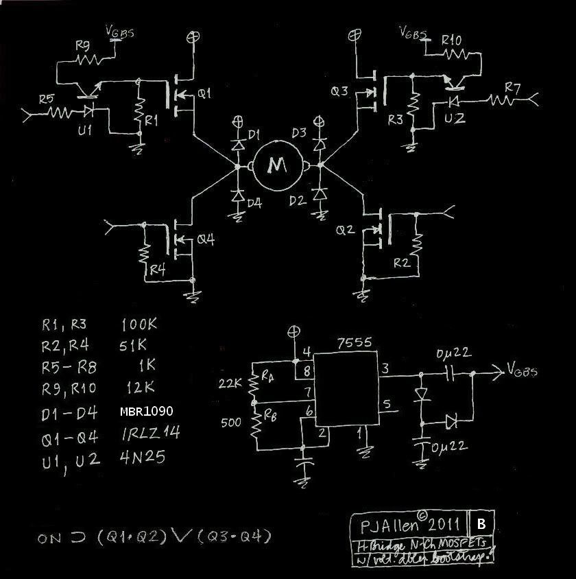
Changed the plain ol' Si diodes for MBR-1090s (90V, 10A Schottky).
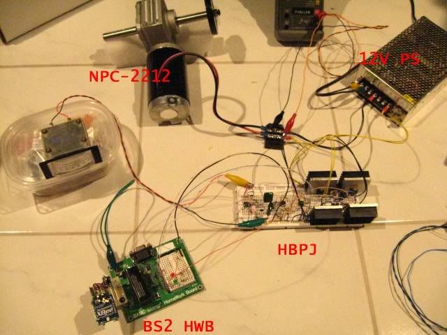
Began dynamic testing using a BS2 HWB as my control/pwm source.
In my static tests I was turning on the high-side and low-side together. In dynamic testing that was making for considerable low-side FET heat. Then I programmed the BS2-HWB to do the proper thing: enable the high-side first and then modulate the low-side. That's the ticket. Running about 100 Hz.
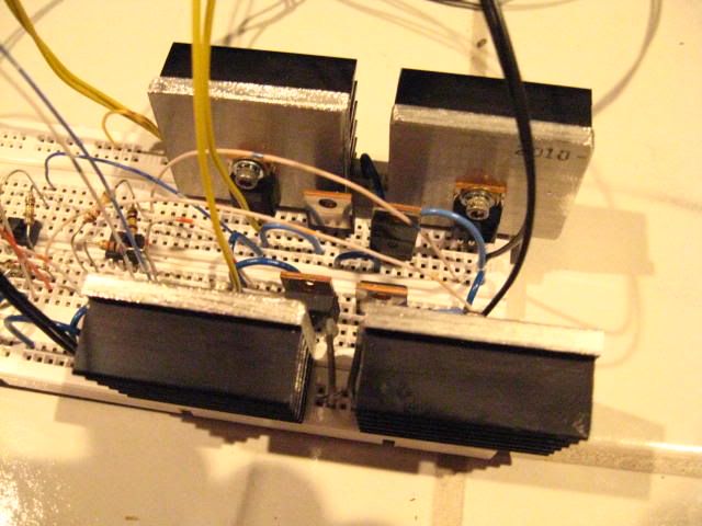
I'll get a video done in the next couple of days (maybe tomorrow?), but following are a couple of pics in the meantime.
Here is a close-up of the new heatsinks; the new diodes (TO220-like pkgs) are there, too.
071111 Update:
OK, here's the video
071311 Update:
Oscilloscope set-up: Ch1 to bridge Term_1 and Ch2 to bridge Term_2; using Add function.
This way the bridge output is more readily apparent, the lower part of the trace is the bridge output. It's just a little less than 12 at low duty and hangs right around 11V. Not half bad.
I need to get this stuff up off the floor! It's nice having it out on the fire-proof tile and nothing falls either, but it's straining the lumbar.
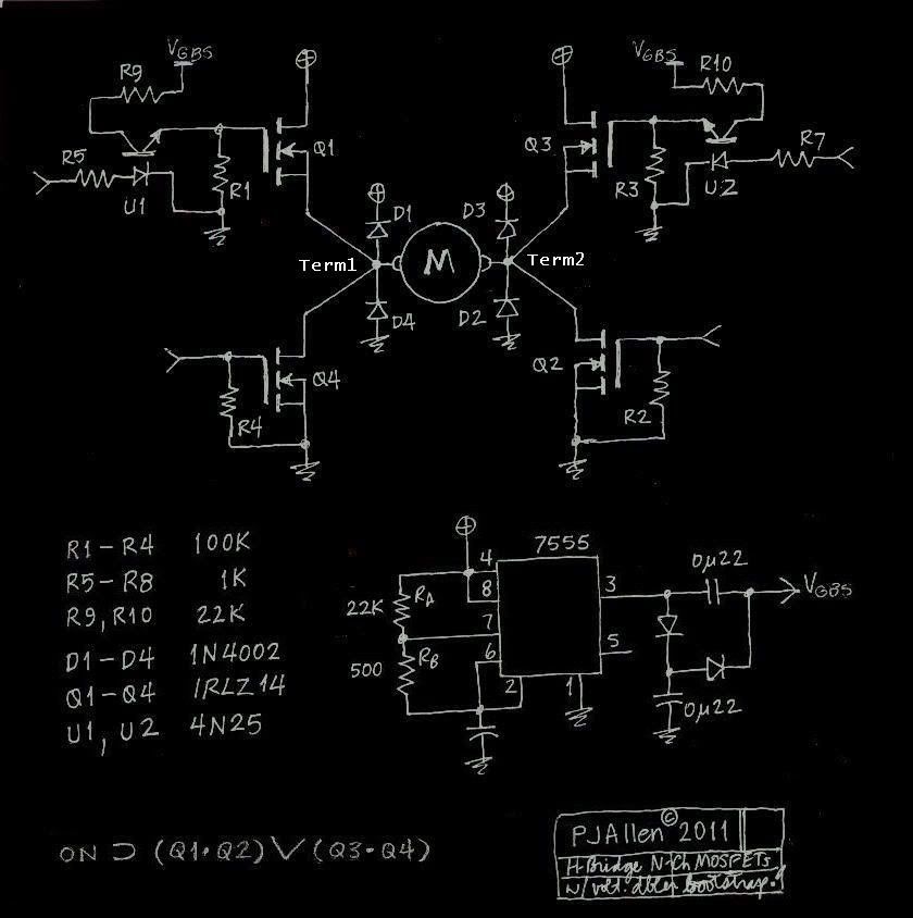
071411 Update:
Here's the current schematic. The layout hasn't changed, but I made changes in some resistor values (R1/R3 and R2/R4) and the diode change (to Schottkys.)
072111 Update:
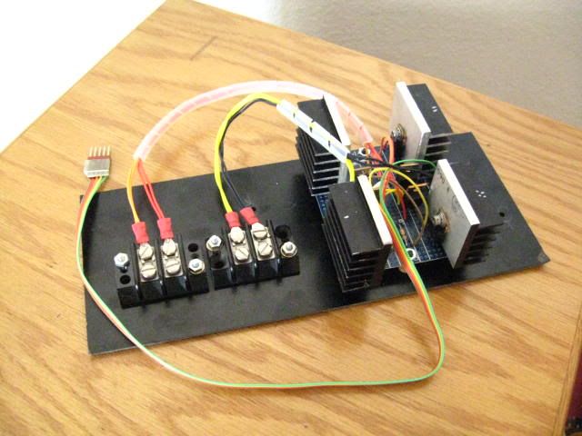
Been working on transferring everything to a piece of vectorboard.
First I had to drill & tap each heatsink for a mount - a screw and a spacer make it rigid enough.

Then it was just a matter of bending wire and soldering.

Everything has tested right as before, slightly improved by soldering vs. the breadboard connectivity.

080311 Update:
I put the H-Bridge on hiatus while I got busy working with the remote controlling of Cypherbot.
I have since made the control board. It tested good (low-level), but I haven't integrated it with the power board (above.)
Here are some pics:


Arduino, H-Bridges, and the Madness of Crowds
There's a big problem at the Arduino Forum (Big!). Every time somebody brings up "making an h-bridge with transistors" that subject will get scuppered by maniacs: subject-changers, side-trackers and other hijackers; dopes and gas-passers who want to "engineer" the silly thing to death; and (worst) the cry-babies, the know-nothings, and the proudly and hopelessly stupid. It doesn't help when the "OP" is an ignoramus, let alone a mentally unstable ignoramus, but that's not a reason for hysteria, hurt feelings, or anyone's virtually running naked through the streets.You are responsible for your own self-esteem, nobody's obligated to indulge your conceit. If you can't hack the deal, if thinking is too hard, that's OK - but find something else to do.
So, in my mission to cast out the Demons of Ignorance evermore...
An all-transistor, all-NPN, h-bridge is not an impossible thing. It's not trivial, it's not ideal - but so fucking what - especially when it's for some fuckwad POS Mabuchi (et al.) motor? Like you really, really need opto-isolators (a/k/a the panacaea of fools) and milliohm MOSFETs for such a thing? [Get well soon, you over-invested shithead.]

So, there's the circuit: you provide a HI to _EN and PWM the corresponding _Spd. To change directions: same process, other terminals - turning the former off FIRST. For the situation presented, it's passing fair. If you can't wire it right - Tough. If you can't work the "sketch" - no es mi problema.
The Demo Sketch:
// hbtool_01
//
//
byte A_Dir = 8;
byte B_Dir = 9;
byte A_Spd = 10;
byte B_Spd = 11;
byte motoff = 13;
void setup ()
{
pinMode (A_Dir,OUTPUT);
digitalWrite (A_Dir,LOW);
pinMode (B_Dir,OUTPUT);
digitalWrite (B_Dir,LOW);
pinMode (A_Spd,OUTPUT);
digitalWrite (A_Spd,LOW);
pinMode (B_Spd,OUTPUT);
digitalWrite (B_Spd,LOW);
pinMode (motoff,OUTPUT);
digitalWrite (motoff,HIGH);
}
void loop()
{
// running DIRection A
digitalWrite (motoff,LOW);
digitalWrite (A_Dir,HIGH); // enable A
analogWrite (A_Spd,50);
delay (2500);
analogWrite (A_Spd,100);
delay (2500);
analogWrite (A_Spd,250);
delay (2500);
digitalWrite (A_Spd,LOW);
digitalWrite (A_Dir,LOW); // DISable A !! or Die! ?
digitalWrite (motoff, HIGH);
delay (1500);
// running DIRection B
digitalWrite (motoff,LOW); // enable B
digitalWrite (B_Dir,HIGH);
analogWrite (B_Spd,50);
delay (2500);
analogWrite (B_Spd,100);
delay (2500);
analogWrite (B_Spd,250);
delay (2500);
digitalWrite (B_Spd,LOW); // DISable B !! or Die! ?
digitalWrite (B_Dir,LOW);
digitalWrite (motoff, HIGH);
delay (1500);
}
Pictures:


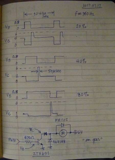
2016JUL17
Here are the waveforms (notes) from the Esplora experiments (main blog), note Collector voltage in the Off state (Base voltage = 0).
with the motor capacitor -
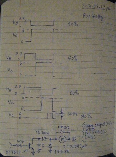
without the motor capacitor -