Saturday, October 20, 2012

PMB-688 GPS


The Polstar PMB-688 is a great GPS receiver. Though its documentation is less than a cup running over, it's knowable nonetheless.
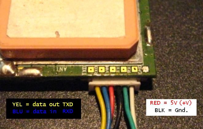
From what I've seen, getting the wires right is the biggest problem. I think that that stems from a general and disheartening disregard for the documentation ( Polstar PMB-688 [PDF Alert] ), substituting for it an intellectually conceited, and lazy, conflation of the silkscreened labels by the square pads above the connector with the wires coming out of the connector assembly. So, here it is, unequivocally: Those labels DO NOT correspond to the connector wires!


Click pic to enlarge.

You don't have to believe me - Get out an ohmmeter and trace the wires to the pads.

The PMB-688 has only TTL I/O available. The Yellow wire is data out (TXD) and the Blue wire is for data in (RXD).
The Red wire is for +5, the Black wire is for Ground.

(It works out like this for the PMB-648, too, but "RS232" TX/RX are available on it.)

Here's the document's wiring diagram and an enhanced version of my devise beside it.


22 OCT 2012 - Had it on the oscilloscope, over the supply range of 3 to 5V, TX was 0/3V signal.

26 OCT 2012 - My only interest for a certain project is the RMC sentence.  The '688 default config is with GGA. GLL, GSA, GSV, and RMC enabled.  Heretofore, I've used the SiRF Demo, solely, to configure the '688 with.  The sentences can be disabled from the SiRF Demo, but if the GPS is left unpowered for 2-3 days then it reverts to stock config.
Q) What to do?
A) Make the config part of the initialisation in the programme.
Q) How's that?
A) Send the following data (4800 8N1):
$PSRF103,0,0,0,1*24<CR><LF>  --  disables GGA
$PSRF103,1,0,0,1*25<CR><LF>  --  disables GLL
$PSRF103,2,0,0,1*26<CR><LF>  --  disables GSA
$PSRF103,3,0,0,1*27<CR><LF>  --  disables GSV
and, if for some reason you need to
$PSRF103,4,0,0,1*20<CR><LF>  --  disables RMC
<CR> is Carriage Return, ASCII $0D (or 0x0d), or \r
<LF> is Line Feed, ASCII $0A (or 0x0a), or \n
The number after the asterisk is the checksum.  I found a great tool, it's at -
 http://nmeachecksum.eqth.net/
Another invaluable GPS site, most everything about anything NMEA --
http://www.gpsinformation.org/dale/nmea.htm
Saturday, October 6, 2012

High-side Switching


A lot of people feel, howbeit superficially, that they "get" NPN operation - the NPN conducts when its Base is at a potential more positive than its Emitter. Understanding a "high-side switch" supposes knowledge of PNP transistor operation.
Comparatively, the PNP is a little understood device. Looking back at some textbooks, they're never presented inside the "+V and GND" paradigm. The PNP is presented with an electrode connected to a negative voltage (gasp!), which provokes apoplexy and panic, or it gets mentioned in passing ("..there are PNP transistors, too, but you won't see them much and I don't like them, so let's move on..") and so is left to languish in obscurity, something to be avoided (ley de hielo.)
The PNP conducts when its Base is at a potential less positive (more negative) than its Emitter. Equally important, but what's not grasped, is that it does not stop conducting till its Base is at or near its Emitter - just as an NPN does not stop conducting till its Base is at or near its Emitter. When the PNP's Emitter is at +12V, you cannot turn it off by presenting +5V to its Base - because 5V is still less positive than Emitter potential (in fact, 7 volts less positive).

Here our PNP is configured Common Emitter (and definitely not to be confused with an "Emitter Follower" - a/k/a Common Collector). It's a "high-side switch", it opens/closes the current path to +V.


The NPN switches the PNP's Base.  The output enable, the input to the NPN's Base, is a logic-level signal from a microcontroller.
The 22KΩ pull-up to +12 biases the PNP off.  When the NPN is biased on, its Collector goes to Ground, taking the PNP's base, via its RB, to Ground (a potential much less positive than +V) which turns it on.
The PNP's IB = (+12V - VBE) / 4K7.  The PNP IC, the current available to the load, is basically = hFE * IB
When little current is drawn, VCE is negligible.  As IC increases, so does VCE.  In my test circuit, using a 2N3904 (NPN) and a 2N3906 (PNP), VCE was 200mV when IC = 200mA.
Potential applications:

  • an "anode driver" in a LED matrix
  • a MOSFET driver 
  • in an H-bridge  

The advantage over grabbing something ULN/UCN/UDN is that you may likely have these components on hand. Hey, RadioShack still has packs of PNPs. And consider, if you get careless or push past the envelope, it's more expensive to replace a whole IC on account of one smoked section than for a single transistor.
And, you learn something.