2018APR15
Began making a "bluetooth speaker". Using a BT receiver I found for sale on Groupon. It has RCA outputs and an 1/8 inch stereo jack for audio out as well as USB-B micro and USB-A jacks, too. The top wasn't difficult to remove, though a couple of screws are hidden. It doesn't have a battery, unlike the very small units you may find. From the description I thought it had a battery, being kind of heavy that way, but it has a weight placed inside without which it's very light. It worked well with the Grundig.
Wired out the BT pairing (red) and status (blue) LEDs as well as the main pushbutton, which serves as power and as a means of initializing pairing and re-establishing a BT connection, for relocation on the speaker's front panel.
I'm going to build an amplifier for it using the LM4871 (*2) which is designed for 5V applications. Not certain whether I'll have a panel-mounted pot because I won't know how much actual gain it has, how much control I'll need, till I build it. I am satisfied that the concept is sound, based on my test using my Archer amplifier.

2018APR21
Built up one experimental channel of the LM4871 amp on the old breadboard.

Decent volume with 20kΩ R_fdbk, but better with 33kΩ. No "0.39µF" for that input cap, but there's a range given for that (0µ1 to 0µ47) - so I used two 0µ1 in parallel [0µ2].
I didn't bother with the 'Shutdown' pull up, just tying pin 1 to GND.
Knocked out the speaker panel. Soft maple is a lot harder than soft pine. I don't have a scrolling saw or anything like that, and my single-speed jigsaw is only for super-hack, so I drilled holes around the speaker hole borders. Plan A was to remove the rest with a chisel, but chiseling with the grain wasn't working out so great and across it may as well have been rock (too much work). Plan B was rasping out the rest to fit. Cannot complete the job till the grille fabric, held up in post, is delivered. (It was "mis-sent", that's official USPS lingo, to another post office and has languished several days there already.)
There was a little chip-out, but a bit of grille cloth can hide a multitude of sins - assuming it ever gets here.


2018MAY11
Went with a sort of cross between "dead bug" and "manhattan" methods by cutting out 'islands' (instead of gluing down isolated pieces).
I didn't order any components, drawing strictly from accumulated inventory.


2018MAY13
Amplifier test 100% success, no "issues".
Continuing with the speaker panel, I glued some grille fabric but it has some sag; not terrible but anyway. Using some 'modern' synthetic fabric, black, which needs to be stretched out, somehow, but I couldn't think of a way to do that. Maybe there's a method on the web somewhere ("instructables"?).
Still haven't tested it all powered from the intended, 2-outlet USB "cube," - been running the BT-RX from that, with the amp from a separate linear power supply.
I found some brass fender washers to use as bezels around the front panel knob holes. I found some inserts coarse threaded external with machine thread internal, but decided to fix the speakers to the panel just using wood screws. The 'inserts' were a total pain in the hole.
2018MAY20
Completed the mounting of the speaker panel.

Cut, drilled and screwed in two struts. Gluing the struts would have been easier but would likely have made their removal destructive. I haven't altered the cabinet, I've really wanted to avoid anything like that - though I had to bore ever so slightly the 4 existing holes for the dial bezel for the LED/LCD bezel. I thought that I had 8 screws, but I only had 6, so I used hot-melt on the brackets between the struts and the panel.
[The seller wanted the cabinet sold or "it's going to Kutztown".]

Full USB Power success, both with the "cube" and the 5V rechargeable. I made a USB_A cable for Amp Power that plugs into the USB_A receptacle on the BT-RX ─ so only one full USB cable is needed (a USB_A to USB_Bmicro). Having the 5V rechargeable option makes it completely "wireless".
The sound is great, even better than I had anticipated.
I need to place the BT-RX and the amp board on a panel and commit to some finalized wiring. Everything is loose and alligator clips, rigged temporary.


Remaining on the to-do list are:
- routing and mounting the Status LED and pushbutton to the cabinet front panel
-
building and testing theLED panel (threshold detector) circuit [Built, tested, but undocumented ─ as yet]
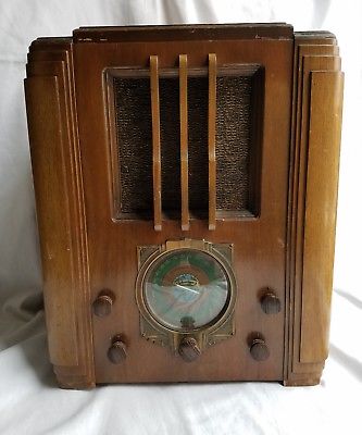
Of note - the cabinet is a Silvertone Model 1955 (c. 1936). Silvertone was the Sears store brand for their radios and, later, TVs and other home entertainment electronics. Here is a picture I found of one that's survived. They're 18 inches tall (2,160 cu. in.)
2018JUN14
Here's the first version of the threshold detector ─

> > Have to add that that design is based on a circuit used in a Sharp/Optonica cassette that I once owned (a "peak" LED that went along with the VU meters). Really lazy "design", needs more work.
And I'm not liking how it's putting the first transistor circuit in the Amp/LM4871 feedback loop either.
I'll keep the diode-Or'ing on the input, to an op-amp buffer and then a comparator, the output of which will feed into a cap/hold-up circuit (better than) above.
2018JUN24
Here's the improved circuit. It has a nice fade-out, less blinky.


Yesterday was a long build session, but worth it. "Phase 1" is now Complete.
Here is the threshold detector / LED driver [TDLD] board --

Here is everything placed in the cabinet --

Here's the front --

The speaker panel can be seen there despite the grille cloth, but only when seen through the camera.
Tomorrow I will upload a demo ("do not leave town!").
[Special Thanks to Dennis Zhang for lasering the 'dial plate'.]
2018JUL24
