It's a strange critter. I guess it's intended for people who wanted to experience the deal but are intimidated by working with electronics even to the slightest degree.
It has onboard pushbutton switches, a joystick, an accelerometer, a little speaker, a photocell, and an RBG LED (probably some other stuff I'm forgetting.)
Those things are all accessed with special Esplora commands.
It can be used, as a Leonardo, to send keyboard codes (use the Keyboard.x commands.)
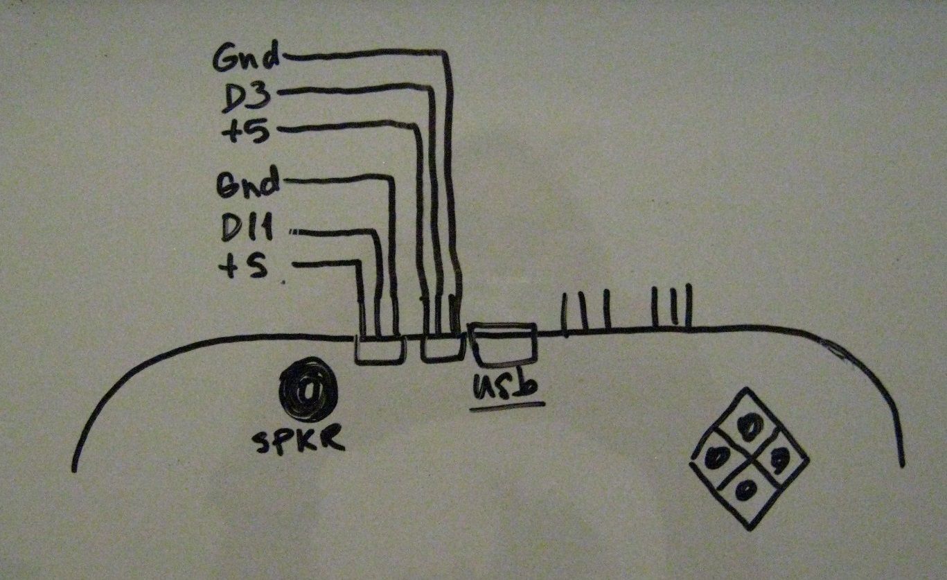
There are 9 digital I/Os available on 3 headers: 2 on two different 3pin headers (orange) and 7 on the 10pin LCD SIP. 2 Analog inputs are available on two other 2pin headers (white).
The analog inputs, the photocell, mic, joystick and the 4 pushbuttons are accessed via an onboard multiplexer which is completely different from the "analogRead" ADC of the familiar Uno (Duemilanove, &c.) paradigm.
The digital pins, though, are configurable as inputs/outputs in the pinMode / digitalRead / digitalWrite scheme. They are, still, microcontroller GPIOs.
I have found that the digital pins work with Servo.h.
More later.
14MAY2016
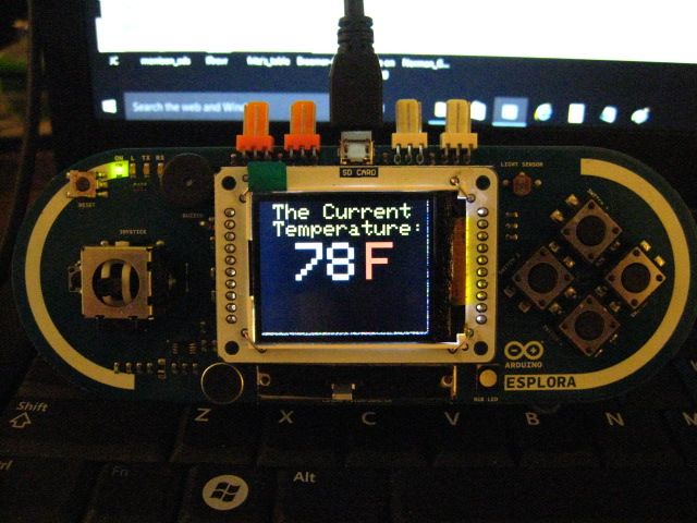
Bought a couple of TFTs on ebay, designed to fit the Esplora headers. $10, not too bad. I think the alignment is off 1 pixel or something, you can see the bright line there on the right and the bottom.
Current draw: 60mA.
03JUL2016
- Softwareserial.h is Esplora compatible.
- Also, the Esplora ADC reference is very supply dependent, it is == supply voltage. As V_usb varies from PC to PC, so too will ADC results.
- The L LED is accessible as Pin 13. Make its pinMode an OUTPUT and then it's digitalWrite-able. It may be possible to hack it into another Digital pin by removing the LED. (None of the left TFT header's pins gets used, so it could be jumpered over there.) Its cathode is at GND, there is a 1kΩ (R-pak) between its anode and 5V.
16JUL2016
The "Tinkerkit" outputs, at least, are supposed to be compatible with analogWrite. I am sure they are, but with my little experiment today, I can confirm that "D11" definitely is, with a period of 1.04msec (960Hz).
I am lazy and didn't write my sketch to check "D3" (maybe it's a different freq/timer used?). I will update when I have more info.
17JUL2016
More experimenting, less about the Esplora and more about the motor circuit. Added motor capacitor to improve the Collector voltage condition in the Off state. The same goes if using a MOSFET (the Drain voltage condition in the Off state.) Go over to H-Bridge & Motors page for more info.
The sketch includes a brief 2.2kHz (50%) interval. You'll see that in the scope trace and the Esplora blue LED goes On.
22JUL2016
The Adafruit Neopixel library is compatible with Esplora.
My experiment used D11.

11FEB2018
Adding the following links (resources) ─
https://www.arduino.cc/en/Guide/ArduinoEsplora
https://www.arduino.cc/en/Guide/ArduinoEsploraExampleshttps://www.arduino.cc/en/Reference/EsploraLibrary
https://www.arduino.cc/reference/en/language/functions/usb/keyboard/
http://learn.linksprite.com/wp-content/uploads/2013/11/arduino_esplora-pinout_diagram.png
https://www.arduino.cc/en/uploads/Main/arduino-esplora-schematic.pdf
https://forum.arduino.cc/index.php?topic=143028.0
Leonardo library is useful too.
20FEB2018
Changed resistor values for more gain and usable range vs. ADC. (New values for R1 and R5 in bright red.) The gain is now "221", (220k/1k) + 1, much better results [IMHO].

Confirming that the RGB LED elements can be set outside the Esplora library (writeRed, and so on) using digitalWrite and analogWrite. Green is D10, Blue is D9, and Red is D5.
If you need more outputs and you're handy with a soldering iron, you could remove the RGB LED, which is a 'common cathode' device. There are 1k resistors between the microprocessor pins and the RGB pads. Those resistors are part of a surface mount pack, very fine pitch.
They should be configurable as input pins too, stands to reason, but I haven't tried this.
01MAR2018
OK with WS2801.
I soldered up a custom interface panel and got Esplora, the LED strip and the power supply interconnected with some crimp caps and a few hacked jumper assemblies. The space between the "tinkerkit" connectors is 0.2in, so a 7 pin header can span the two of them. 2 outputs pins are required to operate the WS2801.

28DEC2018
Engaged in managing a project where an Esplora features significantly - but I won't say more till it's complete. If all goes according to plan, it'll premier before the end of next month, and probably as a Post of its own.03APR2019
And away we go...
http://incredulist.blogspot.com/2019/04/commodore64-meets-arduino.html