It uses an Arduino to control the TRIAC gate firing.

The situation here is: 120 vac, 60Hz.
This is an application of what's known as "random fire" (or random-firing) technique for full phase control. The term random is kind of misleading. Dimming cannot be effected by triggering the gate indiscriminately; triggering (firing) must be done synchronized with the line frequency. The line frequency is detected by finding the zero-cross, the point where the line voltage is at or near zero, which occurs with each alternation (half-cycle).
The resistor on U1's input (between AC Line and U1 pin_1) is 18.6 kΩ. I used 3 6.2 kΩ (1W) resistors in series. [The value wasn't specified on the schematic, prompting my doing so here.]
The Arduino gets zero-crossing pulses from U1's output at D2, one of its hardware interrupt pins.
The delay angle is selectable via two DIP switches. The default is 1 msec and the DIPs are binary weighted [i.e. delay time = 1msec + 1, 2, or 3 msec more.] With that, the conduction angle can be set to approximately 158, 135, 112, or 90 degrees.
Obviously, more resolution could be had with more switches, that's academic enough, but my objective was not some high degree of (or seemingly continuous) variability. This is a research project and these few well-defined options are sufficient.
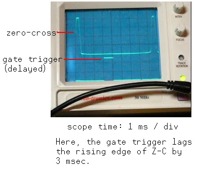
The zero-cross signal is awaited, its occurrence initiates the Interrupt whereupon the DIPs are read and thereby the delay time determined, then shortly the Gate signal pulses after the appropriate delay time and the process repeats.
As there's a snubber across the TRIAC and a snubber for the gate, too, I do intend to try it all out with a fan. That's my plan. But I confess that I'm squishy on it right now - preferring to bask in the glow of my present success before plunging into a power factor situation.
Before that, though, I want to take some pictures of the TRIAC output on the scope.
// *** Triac_03 ***
//
// It's Working! 17 NOV 2012
// gateEnable output lags
// Triac_cue [zc] by 1-4 msec
// via DIPSW1,2
//
byte gateEnable = 3; // alias output
byte DIPSW1 = 4; // alias input
byte DIPSW2 = 5; // alias input
byte GatePulseTime = 1; // at or near Alt start
int timesel;
volatile boolean zeroCrossed = false; // flag
void setup()
{
pinMode(DIPSW1, INPUT);
pinMode(DIPSW2, INPUT);
pinMode(gateEnable, OUTPUT);
attachInterrupt(0,Triac_cue,RISING); // Ext_Int on D2
}
void loop ()
{
if (zeroCrossed == true)
{triacTrigger();}
}
// ----- The Interrupt -----
void Triac_cue ()
{zeroCrossed = true; } //
void triacTrigger ()
{
DIPread();
delay (GatePulseTime);
digitalWrite(gateEnable, HIGH);
delay (1);
digitalWrite(gateEnable, LOW);
zeroCrossed = false; // flag reset
}
void DIPread ()
{
GatePulseTime = 1;
timesel = digitalRead(DIPSW1);
if (timesel == HIGH)
{GatePulseTime = GatePulseTime + 1;}
timesel = digitalRead(DIPSW2);
if (timesel == HIGH)
{GatePulseTime = GatePulseTime + 2;}
}
I have been using "TRIAC", my preference. Should I use Triac when it's the first word of a sentence and triac otherwise? A textbook of mine, "Industrial Solid-State Electronics", uses the latter.
26 NOV 2012 The results with a 40W lamp are really good, but managing a string of LED holiday lights leaves much to be desired. At 90deg, they were practically off. I'm speculating, but I think that the LEDs, being a low-current affair, can't make the TRIAC's holding current and end up dropping out prematurely.
26 NOV 2012 (Pt. 2) I ran the LED holiday light string along with a 40W lamp and had much better results. So, it's the holding current - the LEDlights don't draw enough (not one string, nor two.)
27 NOV 2012 So, here's the last on the LED holiday lights. It came to me that I didn't need to use a TRIAC at all. Given the low current of these LEDlights, the triac driver (MOC3023) itself is sufficient. The zero-cross reference is still required and the MOC's logic input has to be kept active for the entire time of the conduction angle.
Here's the schematic of the modification.


N.B. It doesn't use the switches, that part of the original circuit is not needed. It loops through some chosen values, dwelling at each, and repeating the cycle.
[None of the sketches listed or referred to from hereon have need of the DIPswitch circuit.]
byte gateEnable = 3; // alias output
byte GatePulseTime = 1; // delay time till start
// 1 = brightest
byte PW = 0; // conduction angle
int index = 0;
volatile boolean zeroCrossed = false; // Interrupt Note
void setup()
{
pinMode(gateEnable, OUTPUT);
attachInterrupt(0,Triac_cue,RISING); // Ext_Int on D2
}
// ***** ***** ***** ***** //
void loop ()
{
if (zeroCrossed == true)
{triacTrigger();}
}
// ***** ***** ***** *****
// ----- The Interrupt -----
void Triac_cue ()
{zeroCrossed = true;} // !!!
// ---- ---- ---- ---- -----
// ---- ---- ---- ---- -----
void triacTrigger ()
{
fade();
delay (GatePulseTime);
digitalWrite(gateEnable, HIGH);
delay (PW);
digitalWrite(gateEnable, LOW);
zeroCrossed = false; // Reset
index ++;
if (index > 720)
{index = 0;}
}
// ---- ---- ---- ----
void fade () // GatePulseTime + PW must total 8 (8msec)
{
if (index < 120)
{
GatePulseTime = 1;
PW = 7;
}
else if ((index >= 120) && (index < 240))
{
GatePulseTime = 2;
PW = 6;
}
else if ((index >= 240) && (index < 360))
{
GatePulseTime = 3;
PW = 5;
}
else if ((index >= 360) && (index < 480))
{
GatePulseTime = 4;
PW = 4;
}
else if ((index >= 480) && (index < 600))
{
GatePulseTime = 5;
PW = 3;
}
else
{
GatePulseTime = 6;
PW = 2;
}
}
30NOV2012 Still sidetracked on this holiday LEDlight fading.
I knocked out a better "sketch", the fading levels go up/down
byte MOC_logic = 3; // alias output
byte Intensity; // conduction angle
byte startPosition; // delay time till start
int index = 0;
volatile boolean zeroCrossed = false; // Flag
void setup()
{
pinMode(MOC_logic, OUTPUT);
attachInterrupt(0,cueStart,RISING); // Ext_Int on D2
}
// ***** ***** ***** ***** //
void loop ()
{
if (zeroCrossed == true)
{enableOutput();}
}
// ***** ***** ***** ***** //
// ----- The Interrupt -----
void cueStart ()
{zeroCrossed = true;} // !!!
// ---- ---- ---- ---- -----
// ---- ---- ---- ---- -----
void enableOutput ()
{
fade();
startPosition = (8 - Intensity); // "delay angle"
delay (startPosition);
digitalWrite(MOC_logic, HIGH);
delay (Intensity); // "conduction angle"
digitalWrite(MOC_logic, LOW);
zeroCrossed = false; // Reset
index ++;
if (index > 240)
{index = 0;}
}
// ---- ---- ---- ----
void fade ()
{
// not a lot of difference between
// Intensity = 6 and Intensity = 7
if (index < 30)
{Intensity = 6;}
else if ((index >= 30) && (index < 60))
{Intensity = 5;}
else if ((index >= 60) && (index < 90))
{Intensity = 4;}
else if ((index >= 90) && (index < 120))
{Intensity = 3;}
else if ((index >= 120) && (index < 150))
{Intensity = 2;}
// Intensity = 1 is very low
// fade up
else if ((index >= 150) && (index < 180))
{Intensity = 3;}
else if ((index >= 180) && (index < 210))
{Intensity = 4;}
else
{Intensity = 5;}
}
Here's a solid demo, there are scope traces in addition to lights
Here's a scope trace - for good measure (Ha!)

30 NOV 2012 (Pt. 2)
I think that this time I really will get out of the 'holiday lights' tweak.
30 NOV 2012 (Pt. 3) Crap! I have to walk that back some.
I had put the scope away, but I decided to bring it back out and have a look. Despite improved fading over the way it was before, I saw on the scope that it was only conducting on one alternation, asymmetrical. Then I plugged the 40W lamp in with it and it looked even better than the MOC3023 does. It's totally textbook with the lamp plugged into it.
So, one "strand" isn't enough to do it with the TRIAC. My strand takes 20ma. My TRIAC (BCR8N) spec has both holding and trigger current of 100ma, which means a load of at least 12w. Looks like TRIACs with the lowest holding currents are also of the "sensitive gate" type. There are many Standard types, 400V, 25ma - search Digikey.
I am using this particular Triac because I bought a few on a whim once.
[Maybe 5 strings would do it to it, but I don't have that many to confirm. A resistor might fix it, but it won't present the PTC characteristic (cold = low ohms, hot = high ohms), which it seems would be beneficial at low voltage, but maybe not essential, there has to be a substantial voltage present for the LED string to light up anyway.]
Still, no kidding, the MOC3023's
Good night.
01 DEC 2012 Here's a demo of a TRIAC output, the classic wave-forms you expect to see (running from the same sketch above)
Be that as it may, the circuit the TRIAC is controlling needs to be drawing appreciable current or the TRIAC is unhappy. Maybe I should have demo'd that part, too?
* Here I can add, and do confirm, that the TRIAC output is just as solid by pulsing the Gate, at the beginning of the conduction angle - the method used with the very first "sketch" up at the top (it's labelled "Triac 03".)
I made a lot of assumptions about Triacs, I took a lot for granted, but I now have an appreciation for trigger current and holding current, at least I think I have a lot better handle on that than before. Hadn't ever designed with them, they were always a "working or not working" proposition. I certainly had the lamp dimmer going good, then I got sidetracked on the 'holiday LED lights' and got educated almost by accident.
I need to get back to my plan - running the fan. I was reading an app-note from ST and from what I gather, given an inductive load, the Gate should not be pulsed, but held on (given "ELI".)
09 DEC 2012 I still haven't run the fan. But I was making some H11/3023 boards and I used 2K resistors instead of 1K on the 3023 logic/input - and that skrewed it up. I swapped those out with some 470Ω that were on my bench and that brought things right (same as before.) That light-activated SBS is light-dependent for sure, it's like CTR with a photo-transistor output.
22 DEC 2014 Two years later! (Hard to believe.)
I have some VO2223 "power photo-triacs" to try out. I plan to mess around with those this weekend.
I've had the light-string up at work and I developed a new "sketch" - it has two routines for fade up/down (two speeds) and two routines for blinking (fast, slow).
Look for lightstring03 in my Where's The Code? page.
04 JAN 2015 OK, I finally got a VO2223 circuit together. I found out that they need more input current. With a 40w bulb I was only getting 60v when on with 4-5ma input. Running that up to 10ma got me over that hurdle. I need to incorporate this with a zero-cross board of its own.


All constructive Comments are encouraged (and encouraging)!
Thanks for sharing this. One question, what do you mean with 0µ01 and 0µ1 in your diagram? 0.01 µF and 0.1 µF?
ReplyDeleteCan you also shortly explain what the capacitors are for in this diagram? I'm kinda new to this, but I'd like to build this too. Thanks!
Right, yes, 0u01 for 0.01uF and 0u1 for 0.1uF
DeleteA technical writer, Ray Marston, advocated this convention instead of using decimal points (full-stops) because those don't always get marked well, a little point can look like an inadvertent speck or something. Marston's convention leaves no ambiguity, but not everybody is used to seeing it in this form. (:
The 0u1 cap along with the 100Ω forms a snubber network, which is only necessary for inductive loads. The 0u01 has a similar function, vis-a-vis the dv/dt on the triac gate.
Over-rate your components. I used 2W resistors and 400V capacitors (vs. our 120vac line voltage.)
Thanks! One more thing: the resistor at the U1 input, what would you suggest for 220 volts?
ReplyDeleteThe input of U1 is an LED (it's 2 back-to-back LEDs).
Delete10ma would definitely do it, that would be 22K - that's > 2W.
47K, for 4ma, 0.9W, should be sufficient (that could be two 1W, 100K resistors in parallel.)
Let me know how you do.
I hope that you have an oscope, an ac voltmeter, and take this on in steps.
Thanks, I am in the process of getting an oscilloscope (I do have a voltmeter), and I will take this in small steps certainly.
DeleteI hope you don't mind my questions though, but I want to know exactly what to do with 220 volt, no experimenting :)
Can you explain more about the LED(s) at the input? Do they go in series with the resistor (why?) And does back to back mean in series with one of them polarity switched... like -+ +- ?
Thanks for helping me out!
p.s. I'm trying to control a motor RPM, I got the tachometer on the motor hooked up with the arduino last night successfully, so if I can get this to work, then I should be able to control the current dynamically to get a desired RPM.
A representation of the zero-cross detector can be seen on the datasheet --
Deletehttp://www.jameco.com/Jameco/Products/ProdDS/320434ISOCOM.pdf
The LEDs (IREDs), "back-to-back", are in parallel. One conducts during the positive half-cycle and the other conducts during the negative half-cycle. At zero, zero-cross, neither conducts: zero-cross detection. A resistor is required to limit current through them because they are diodes, not lamps.
See, here's "the thing":
The lower that resistance the sooner those diodes start to conduct, which makes the zero-cross ("time of no conduction") period shorter, which results a narrower pulse.
I still have not attempted any motor control, though I think it's ready.
Two 100K 1W resistors should suffice, but a 47K 2W would be "better". The 1W resistors may be more available in your area. [The ratings, "wattages", add - whether in series or parallel.]
I still have not used this to control a fan, as I had set out to, but I think that it is ready. I'm not an ac-motor control maven, as such. I think it's ready, you may beat me to it.
I'm ordering the components now, but I wonder for the triac part of the circuit if I need to use different resistors for that part, because we have 220 volts here? How you did calculate the values of those resistors?
ReplyDeleteThanks!
I got the zero crossing working, but when I tried to control the triac I couldn't get it on at all. I feld rather unconfortable messing around with the 230 volts, so instead I got a tranformer to get 12 volts AC, so I could try on a breadboard with that.
ReplyDeleteNow at least I got the moc3023 working and I made a nice fading program for the arduino. I used float xvalue = acos(1.f - (power/50.f));
delayMicroseconds((PI-xvalue)/PI*10000.f); to find the correct amount of delay based on power (from 0 to 99.9, using 50 hz ac)
This gives a very smooth fading in my test light :) It also looks very smooth on the scope (even though the AC wave is not exactly a nice sinus). Doesn't seem like you're reading this anymore, but thanks anyway for sharing your design :)
I have been reading, but sometimes a guy has to be left to take a couple of steps.
DeleteBy "the circuit", you're referring to that at the top of the page, and not the special 3023 circuit for the LED-based light strings?
I cannot help but think you must have a wiring (connection) error.
Are you using a lamp (light bulb) for a load?
What I didn't know it that it seems to matter which way you connect the MT1 and MT2, I thought they were interchangable. I am now testing on 12 volts with a 100 mA lightbulb, and again I couldn't get the triac on. But then I was trying again and suddenly it worked. Then I noticed I had the MT1 and MT2 the other way around. I am using the triac now without the snubbers. Next step is with 230 volts and a light bulb, and then 230 volts with a motor. Any idea why it matter which way the MT1 and MT2 go? is 100 mA to little?
ReplyDeleteYou're not the first. MT1 and MT2. I don't know why sometimes they're figured interchangeable. They do have different labels, afterall.
Delete[At first they were called A2 and A1 (Anode 2 and Anode 1).]
As for whether 100ma is too little: There is a spec for "holding current" which looks to be about 100ma or so [at 0deg celsius]. That's an expectation of "typical" per the graph, it's a minimum where it will conduct in the absence of Gate bias - which is most significant with inductive loads where current and voltage will be out of phase.
Well from my (beginners) point of view it's not so strange. I am working with AC, so intuitively you think: there is no predefined direction for the current, and the triac is also drawn as a bidirectional unit, so it MT1 and MT2 could be placed either way, because current will be flowing in both directions anyway. Also for the naming, if you compare with a transistor, it has 3 different names for the terminals, but with a triac it is just MT1 and MT2, which kinda suggest they are not different, but just the two main terminals for the main current. Actually, not I think of it, I still don't understand how it can matter which way they go because it's bidirectional, but I won't bother you with it, I will try to read a good book about it :)
ReplyDeleteAs for the holding current, the problem is that it won't even turn on if I switch MT1 and MT2, so not sure if it has to do with the holding current?... but again I will read some theory about triacs to figure out what's going on :)
Great article, this is what I was looking for. Thanks a lot!
ReplyDeleteThanks for sharing your project!
ReplyDeleteWould it work with a brushed ac motor?
I have to keep a motor's speed constant regardless the load it carries. So I have to read the speed with a tachometer, convert that signal into PWM and trigger a triac to compensate the motor's speed (increase the voltage) when the load restrains it.
Do you think this could work?
Cheers!